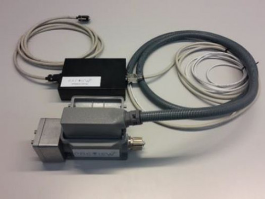
The DAS collects the mould and machine data that is sent wirelessly to a central server to be modelled and analysed. The process of data acquisition is triggered when the injection cycle starts until this ends or reaches the defined timeframe.
The DAS offers the following functionalities:
a) It provides custom built and standardised connection to multi–standard cavity sensors and machines.
b) Injection process data is sampled regularly (100Hz Frequency)
c) It offers traceability: the measured cycle is individually labelled with identification numbers referring to the mould and machine used
d) It enables to acquire the following data per cycle:
• Mould/cavity data: cavity pressure and temperature
• Machine data: screw position, machine pressure, cycle time
• Process configuration parameters: holding pressure, injection speed, set switch over position, plasticizing stroke, start injection position, back pressure.
e) It has the ability to work at wide range of industrial temperatures from -40°C to 85°C.
The functioning structure of the DAS is defined by two main sets of data:
a) Administrative data: which is used to assign a machine, mould and location (IP) identification numbers (IDs) for purposes of keeping track of multiple machines running in parallel and information being sent simultaneously in a wireless network system
b) Technical data: this refers to the signals coming from the machine (e.g. machine hydraulic pressure) and mould (e.g. cavity pressure and temperature)
The data capture by the DAS can be classified as digital or analogue depending on its intrinsic characteristics. Data that varies in a discrete way (e.g. on/off), is recognised as digital, this involves time related data, such as the triggering signal for start/stop of a moulding cycle. Signals that vary continuously over time, such as cavity/machine pressure, temperature and position, are classified as analogue.
The DAS is composed of three main circuit boards to enable the data acquisition and wireless capabilities, these are:
a) ARM main board: packs and resends the captured data
b) Interface board: works as a bridge between the ARM main board and the signal conditioning board
c) Signal conditioning board: manages the adaptation, amplification and analogue-to-digital conversion (ADC) of the signals.
These boards use an Inter-Integrated Circuit (I2C) communication protocol.
| Web resources: | http://plastia.com/intooligent.php |
| Country: | ES |
| Address: | Ceramistes 2, Barcelona 08290 |


